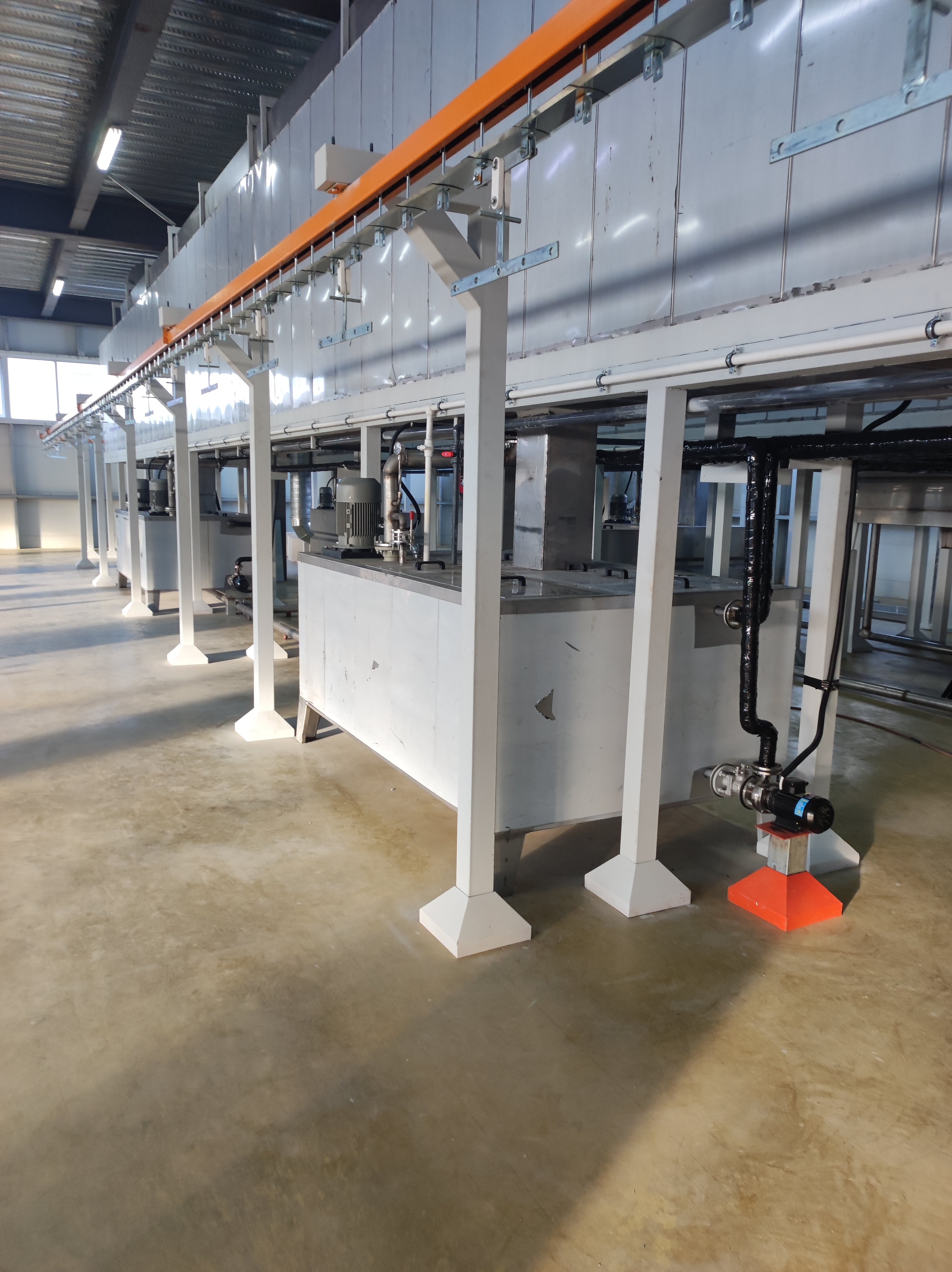
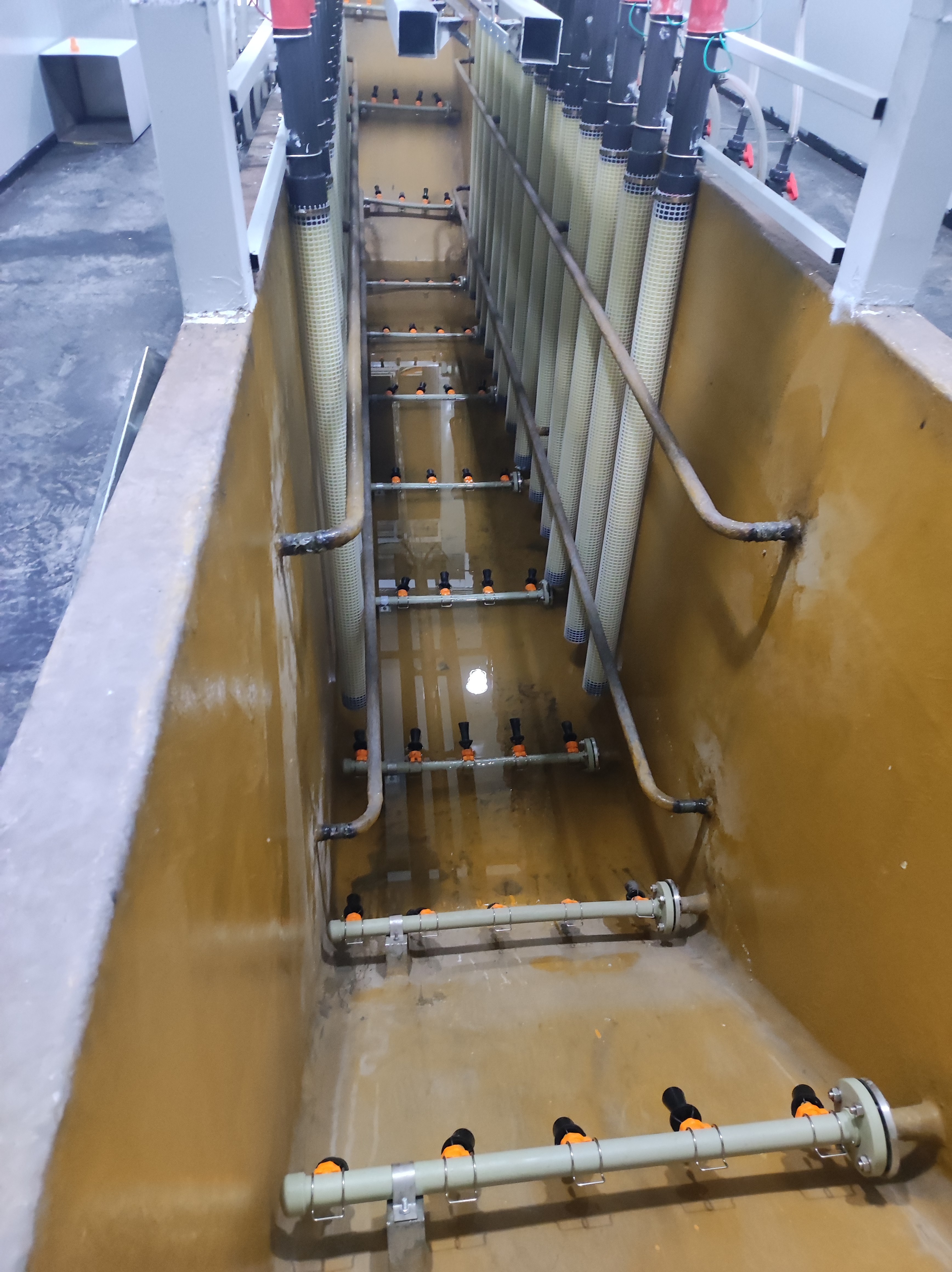
Our company has customized electrophoresis equipment for Algeria's IRS Company. The electrophoresis production line process includes: workpiece loading → rust removal → pre-degreasing → main degreasing → Water Wash 1 → Water Wash 2 → Ceramization → Water Wash 3 → Pure water line → Cathodic electrophoresis → UF1 spray recovery wash → UF2 spray recovery wash → Pure water washing → Draining and leveling → Electrophoretic paint drying and curing → Cooling → Workpiece transfer. Components and Features of the Electrophoresis System: ◆ The electrophoresis tank serves as the immersion chamber for electrocoating and electrodeposition processes, consisting of a main tank and a auxiliary tank. The main tank measures L 11,000 mm × W 1,200 mm × H 1,250 mm; its body is constructed from 5 mm thick SUS304 steel plate with a 6 mm-thick anti-corrosion fiberglass interior, reinforced externally with 100×50 mm flat plates, and features an anti-corrosion coating on the exterior and a solid base. The auxiliary tank is made of 10 mm thick PP board with a conical bottom design. The main tank contains Venturi circulation pipelines and nozzles at the bottom, connected to filtration, ultrafiltration, heat exchange systems, and valves. ◆ Electrophoresis Central Control System: One fully automated control system – an innovative, groundbreaking solution for the electrophoresis industry and an integrated equipment package for electrophoretic processes.
◆ Bag-type filtration system: Features a bag filter with a housing made of electrophoretic corrosion-resistant material; inlet and outlet dimensions are (DNA80*80); external dimensions: Ф600 mm × H810 mm; lined with a corrosion-resistant mesh cover; filter bags constructed from polypropylene felt with a filtration accuracy of 25 µm–50 µm; equipped with PVC piping and valves.
◆. Heat exchange system. Specifications: made of stainless steel; employs a plate heat exchanger for heat transfer.
◆Power circulation system, specifications: A 60-ton/hour chemical-grade circulation pump operating continuously 24 hours per day.
Electronically controlled valves and piping systems.
◆. The electronic control system employs high-quality domestic brand electronic components to ensure excellent equipment performance.
◆. Integrated box design with an aesthetically pleasing appearance, user-friendly operation, and superior performance.
◆ Anode circulation system: 1 set ◆ Ultrafiltration (UF) system: A critical component of the electrophoretic coating process, representing a membrane separation technology. The separated low-molecular-weight substances and water from the electrophoretic coating are termed ultrafiltrate (UF liquid), which is utilized for paint solution recovery and routine tank maintenance.
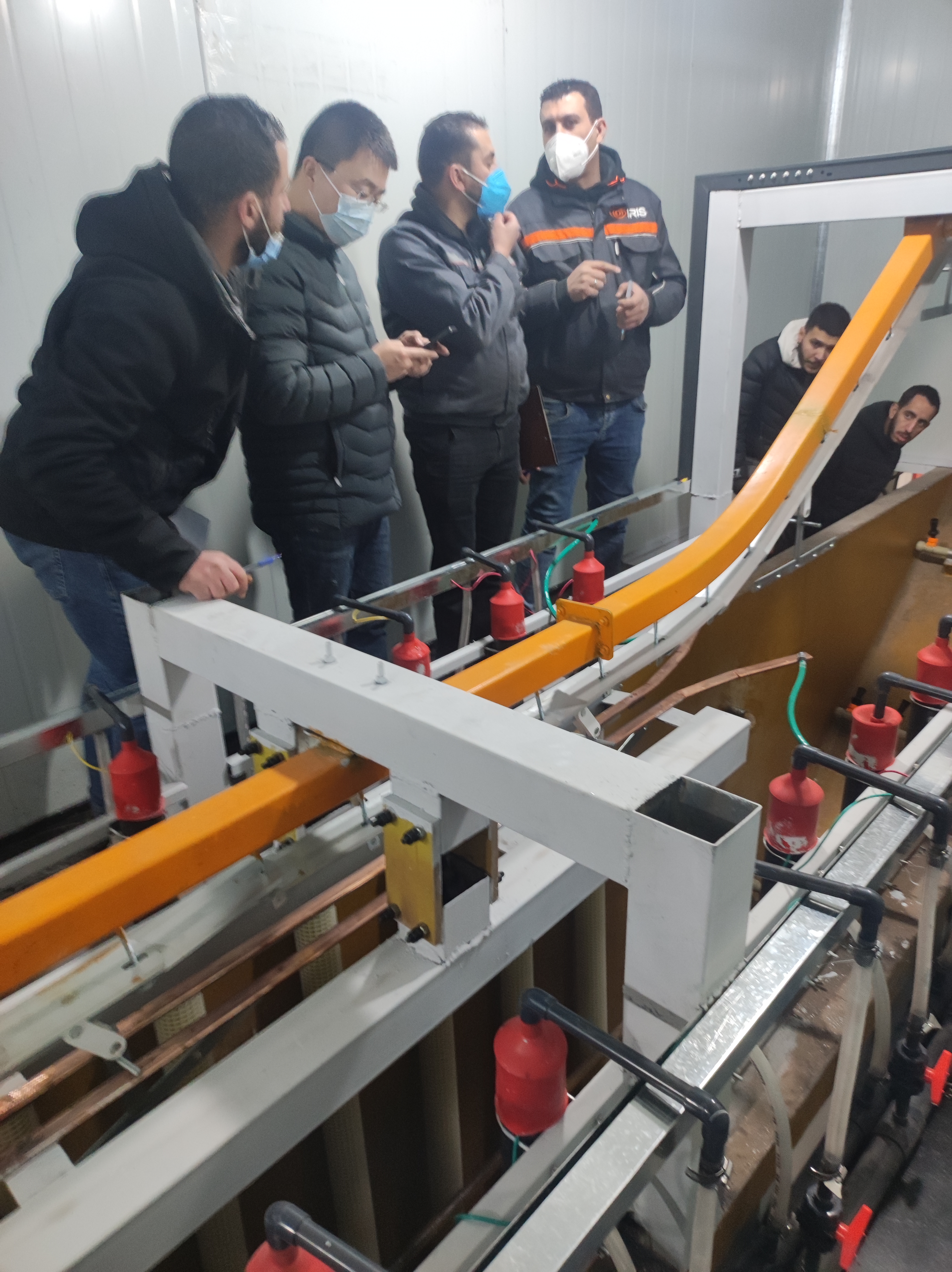
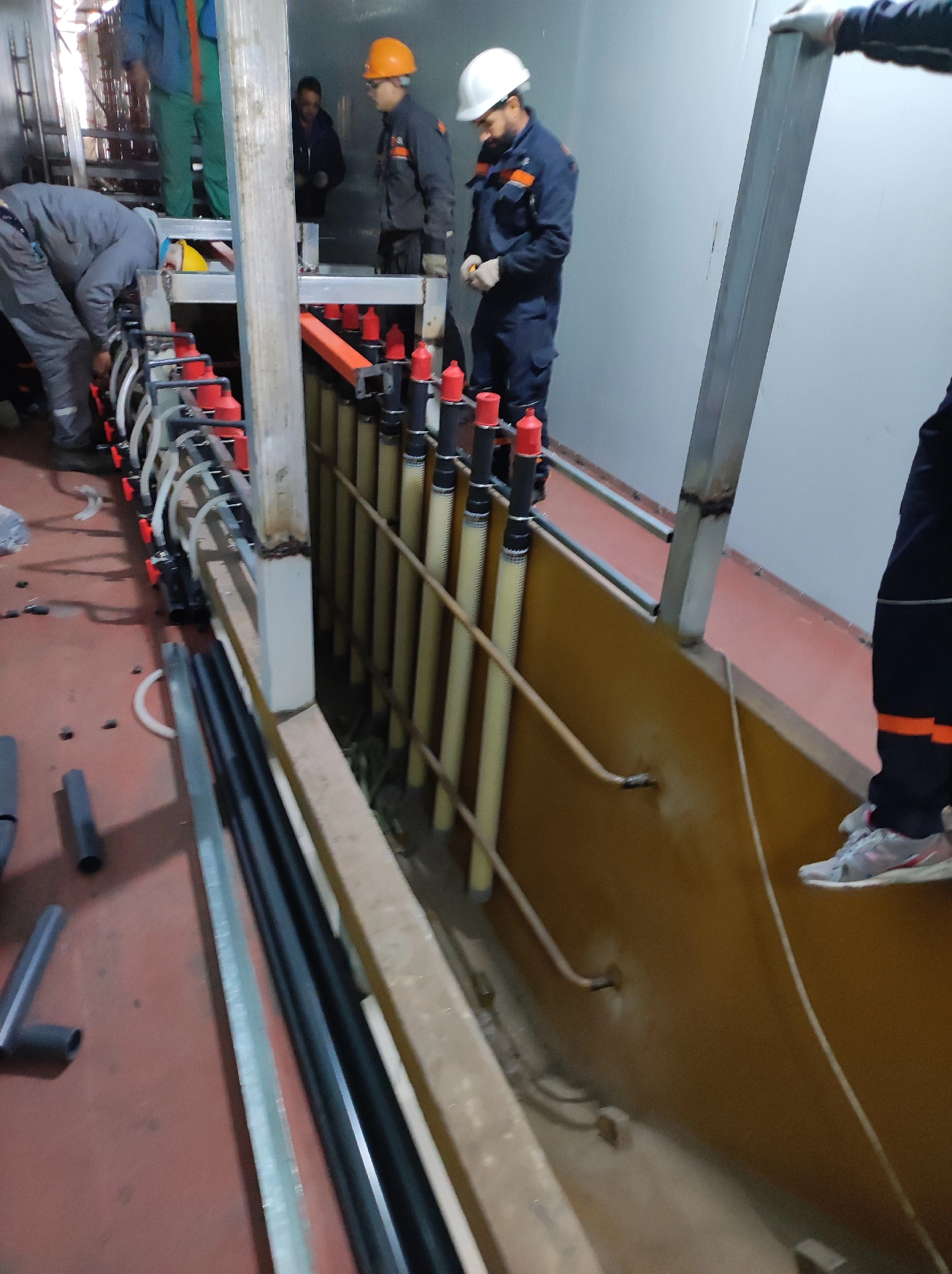
◆ Cathode Conduction System: Electrophoretic coating requires specialized thyristor rectification equipment to convert industrial alternating current (AC) into the required direct current (DC). A 30 kW (300 V/200 A) electrophoretic power supply rectifier is installed, featuring adjustable control, soft start, overload protection, and an alarm signal upon power interruption. The cathode conduction system consists of stainless steel conductive tracks, insulating hooks, and conductors.
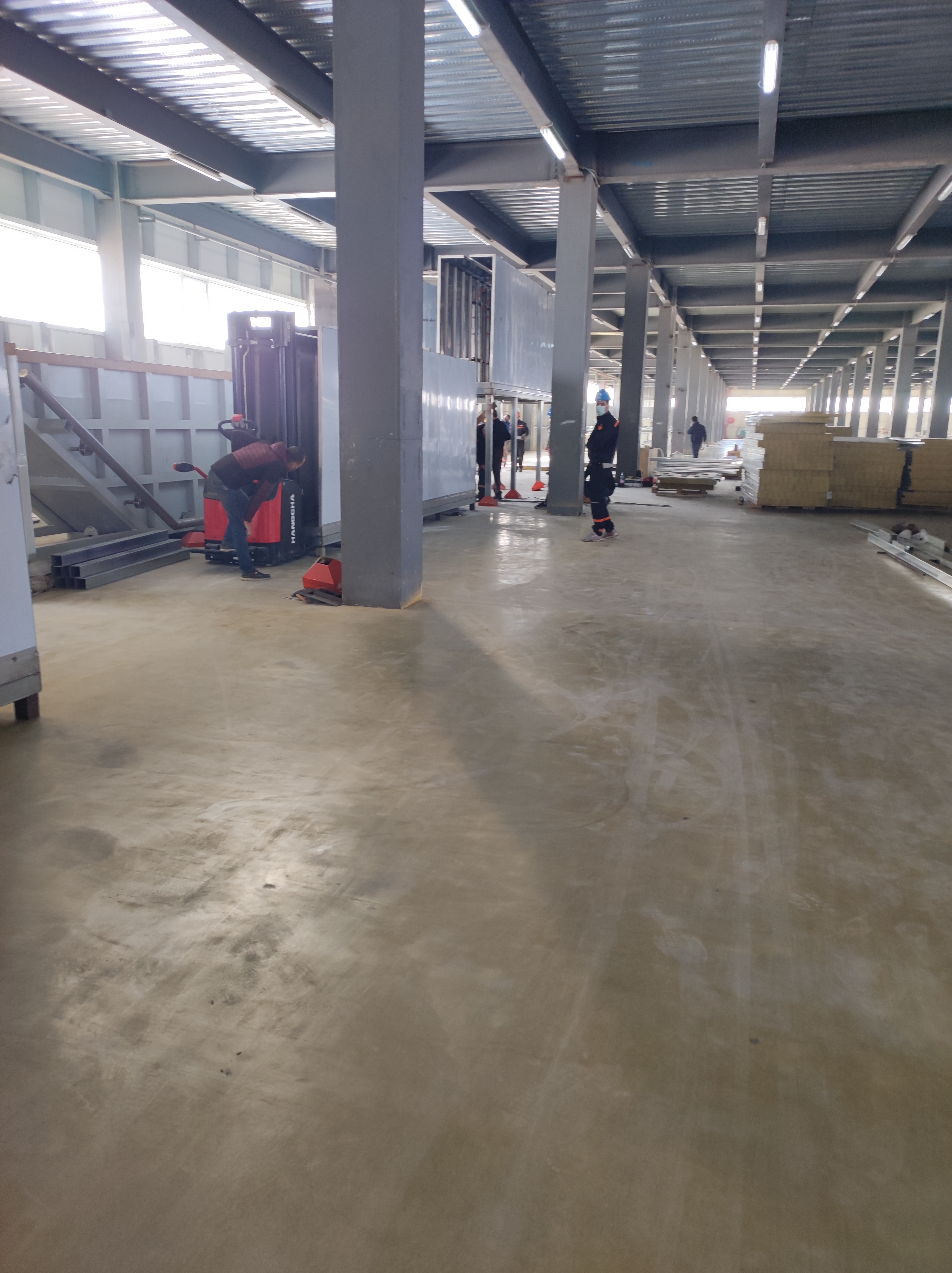
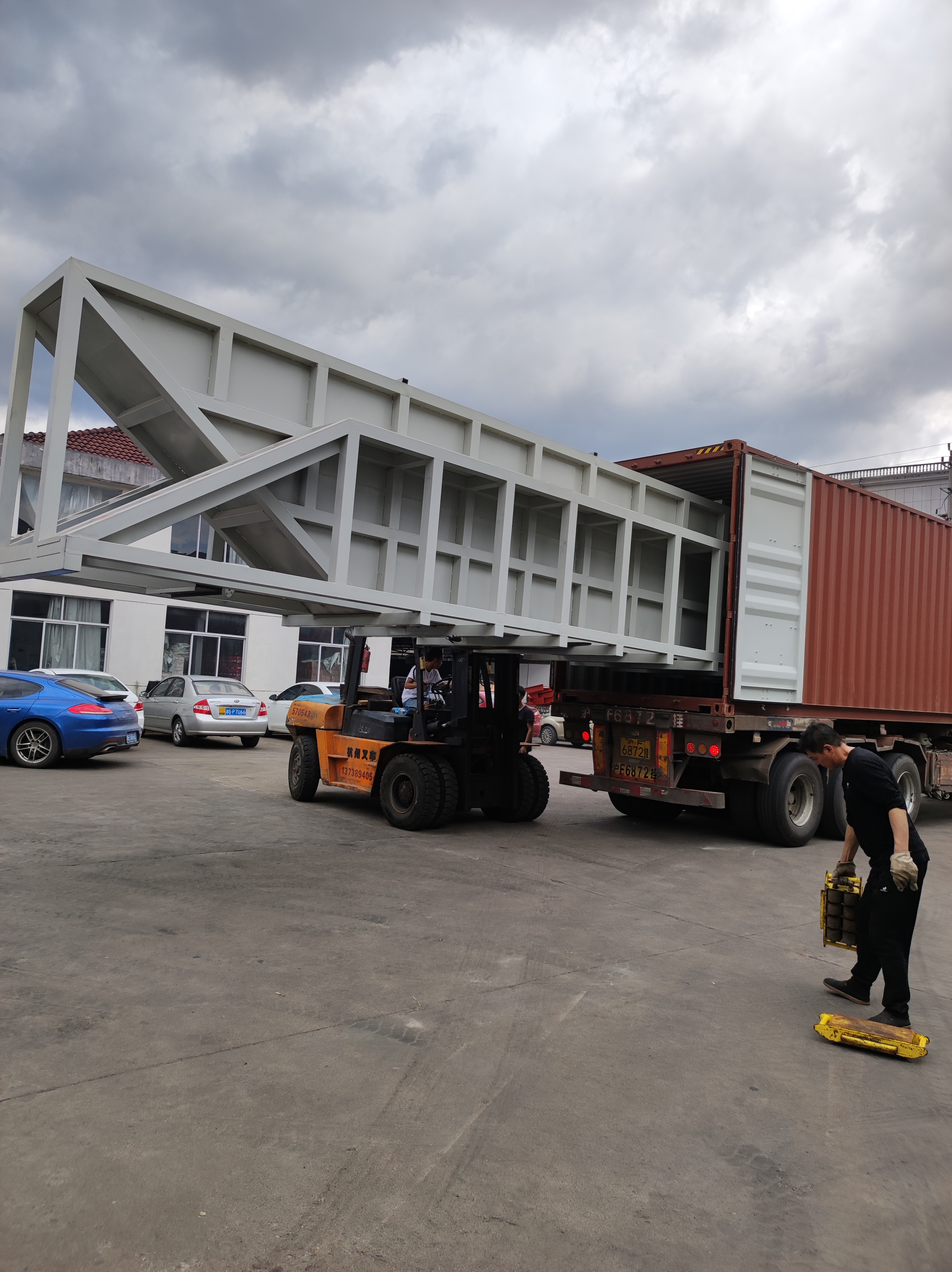
◆Heat Exchange System: Equipped with an integrated heating and cooling system, which functions as follows: The operating temperature of electrophoretic paint ranges from 25–28°C; adjustments to this temperature require heating or cooling. This dual-mode unit provides both cooling and heating capabilities, achieving heat exchange through a dedicated medium to avoid direct damage to the paint components. ◆Pure Water System (2 m³/h): Design Basis: 1. Raw water quality: tap water; 2. Pure water requirement: industrial-grade purified water (conductivity <10 µS/cm). Process Flow: Raw water tank (A) → pressure pump → fine filtration (stainless steel) → ultrafiltration membrane module (membrane method) → purified water → high-pressure pump → reverse osmosis module (membrane method) → pure water → pure water tank (C); wastewater → wastewater tank (A) → raw water tank (B). Equipment Configuration: Electrophoretic paint drying tunnel. 3.1 Composed of an insulated chamber, inlet/outlet sections, air supply/return ducts, base frame, heating system, exhaust device, and automatic temperature control system; 3.2 Main drying tunnel features a raised concealed bridge design with inlet/outlet doors at the bottom, allowing workpieces to enter/exit from the bottom while minimizing heat loss via rising hot air; 3.3 Furnace body constructed with rock wool sandwich panel assembly for on-site installation. The inner wall is constructed from stainless steel plates with a thickness of 0.6 mm, while the outer wall consists of high-quality color-coated steel plates of the same thickness. A thermal insulation layer made of fiber rock wool (with a density of no less than 100 kg/m³) is filled between the inner and outer walls, with a total thickness of 120 mm. The top of chamber 3.4 features a frame fabricated from structural steel to support the chain structure. The furnace inlet and outlet are designed as bridge sections to prevent heat loss from the interior; these sections have a 30° slope and form a continuous structure, allowing workpieces to enter and exit entirely from the bottom for optimal thermal insulation performance.
3.6 The supply and return air system employs a bottom-supply, bottom-return configuration. The main air duct is equipped with a control valve to regulate the drying chamber temperature field, ensuring uniform temperature distribution within the furnace, optimizing space utilization at the fixture base, saving storage space, and facilitating cleaning operations inside the drying chamber.
3.7 All return air ducts shall be constructed from galvanized steel plates, with thickness specified in accordance with national HVAC standards.
3.8 The entire plug-in board is integrated and mounted on the elevated base.
3.9 A direct natural gas heat exchange configuration is employed, with the hot air furnace installed at the bottom of the drying tunnel to maximize factory space utilization and save floor area; 3.10 The drying tunnel is equipped with a forced exhaust system for removing water vapor from its interior. The exhaust fan utilizes a centrifugal type with adjustable airflow capacity, and the ducts are constructed from galvanized steel plates.
3.11 The temperature control system employs a multi-point measurement and single-point control configuration, utilizing platinum resistance thermometers and an intelligent temperature control module for convenient adjustment; the temperature control error shall not exceed ±5°C. The temperature controller is an imported product. 3.12 A temperature overload protection switch and a fan pressure switch are installed to provide dual protection for the combustion system; upon detection of overheating or fan failure, the heating system is immediately shut down with audible and visual alarm signals. 3.13 Maintenance ladders and platforms are provided for easy maintenance access.